Featured Services
Design Engineering
We do design engineering in both the analogue and digital fields. We have designed such things as; Tire Pressure Monitors, Safety Antennas, Control Circuits for lamps, Field Tester for testing equipment in the field, Light Engines for fiber optics, Pulse Width Modulation (PWM) circuits for control lights, Traffic Control equipment, etc.
Eric Neilson and myself (Bill Davis) has well over 30 years each in Designing equipment in the electronic field.
Software Assistance:
- ACAD 2008
- Multisim 10
- Mathcad 14
- Spectrawiz Optical Scan
- Mathimatica 6
- Corel 10
Digital:
- Machine Language
- DMX512 Encode/Decode Design
- Pulse Width Modulation
- Radio Frequency Data Link
Analogue:
- Full Range, Dc to 1 GHz
Costumes Made For Wiring
Section 1
Material Selection:
The type of material used in the making of a costume is best left to designers and people skilled in that art. However, for safety of the person wearing the costume there are some guidelines that would be wise to follow. All electrical wiring should be installed between nomex liners. This would consist of an inner liner that is next to the outside material which serves two functions; (1) To protect the outside material from the wiring and (2) To anchor the wiring harness down to keep strain from being applied to connections. It would also consist of a removable liner which covers the wiring on the inside of the garment and protects the person wearing the costume from the electrical harness. The removable liner will also serve as a washable liner which will help to preserve the costume from body odor. It is imperative that two liners be used within a costume. It is recommended that these two liners be of the nomex material. It is also recommended that the liner next to the pers on be removable by means of snaps, velcro, or hooks.
Costume Design:
There are certain guidelines that need to be followed when designing a costume that is to be lighted. The costume to be wired needs to be completed prior to wiring; This means himed and the detachable liners installed.
The costume piece must layed out in such a way that the electrical harness can be routed to all lamp locations. In otherwords, no hidden panels that the harness cannot reach. A costume is normally turned inside out for installing the wiring and making the solder connections. I t is necessary for the person making these connections to be able to see the connection being made. Therefore, the lamp placement in the costume must be in a location that can be seen in full view when the costume is turned inside out.
Lamp Placement:
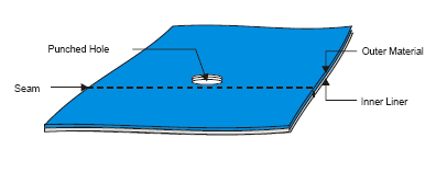
The costume must be marked as a location of lamp placement. In other words, what lighting effect is desired to obtain the customers requirements. The marking of lamp placement is best obtained by the use of a Tack-It Gun which installs colored flag as to location. Different colors of flags can be used to identify placement when the costume is to be wired for color change or different colors of lamps are to be used on the same costume piece. When installing these flags it is important not to puncture through to the removable liner, since the installed grommet is only installed in the outside material and inner liner. It is also important to place the lamps where they can be seen from the back side of the costume, since these lamps are soldered onto a main harness.
Flagging Holes:
When installing flags for lamp placement it is also very important not to install a flag on a seam line, since a hole has to be punched through the material for the installation of a grommet; and when hole are punched in seam lines it may weaken the stitch. It is also important not to install a flag under the arms or between the legs, because of body movement. As a general rule, just use good common sense when placing the flags and keep in mind that a grommet has to be installed at that location.
Tagging Costume:
A tag needs to be attached to the costume which calls out the name of the costume and any special instruction that may be desired. For instance, is the costume Static Wiring (all lamps on the costume turn on at the same time and stay on), Two Circuit Color Change (one color of lamps come on until a command is made to change to the second color), Four Circuit Sequential Chase (the lights chase in a given direction), or Four Circuit Random Chase (the lights turn on and off in a random pattern or what is also known as a twinkle pattern).
Detachable Costume Pieces:
When costumes are built with more then one lighted piece it is necessary to use some means of disconnect between the pieces (This will be covered in more detail in the wiring section of this manual). It is also necessary to know what the distance is between these detachables. For instance, a head piece is detachable from the main costume piece which is trousers only (the shirt is not wired); the distance from the exit of the trousers to the head piece must be known in order to set lead length between these two pieces.
Exposed Harnesses:
Exposed harness that inner tie costume pieces should be covered with some type of cloth tubing. This tubing should be made large enough to snake the harness through it after the costume is wired. Skin colored tubing can be used where the harness may lay next to exposed skin of the person wearing the costume.
Costume Storage:
Costumes should be stored in a cool dry location. The hanger used to support the costume should be of the heavy duty type. It is a good idea to sew Hanger Loops into the shoulders or waist bands of a costume piece in order to help support the weight of the piece when the costume is in storage.
Flame Resistance:
All fabric used in a costume should be flame resistant. If flame resistant material is not available, then the costume should be sprayed with a suitable coating of a flame resistant spray.
Two standars can be used for Flame Resistance fabric.
NFPA-701: Standard Methods of Fire Tests for Flame Resistant Textiles and Films.
CPAI-84: A Specification for Flame Resistant Materials Used in Camping Tents
Costume Cleaning:
Washing and Cleaning solutions should be tested on a sample costume prior to general cleaning. Not only should the fabric be tested but also the wiring and lamps; in order to be sure the cleaning solution to be used with not damage any part of the costume or its wiring.
Grommet Installation
Section 2
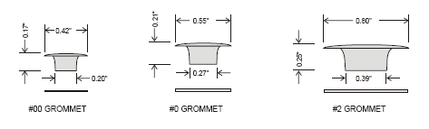
Grommet Types:
There are three basic sizes of grommets used in costumes; These sizes are the #00, #0, and the #2 grommet. The two types of grommet materials recommended for costumes are aluminum or brass depending upon the color of the material used in the costume or customers preference.
- #00 used when installing T1-3/4 LEDs directly.
- #0 used when installing T1-3/4 LEDs in VCC Lens Ass’y.
- #2used when installing Peak Beam Lamp Sockets.
Hole Punching:
Avoid seam lines when punching holes in fabric to install grommets. If possible, shift the hole location to just miss the seam line. Also, it is better to locate hole patterns away from the garments edge if possible.
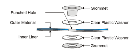
Installing Grommets:
When installing grommets in a costume piece it is important to use clear plastic washers between the metal of the grommet and the costume fabric. This procedure will keep the edge of the metal on the grommet from cutting the fabric.
Wiring Techniques
Section 3
Costume Power:
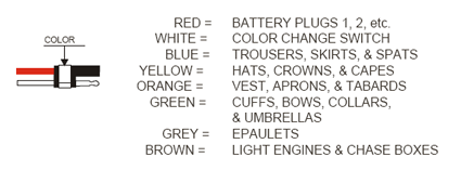
The electrified costume is powered from a 6 volt battery. This battery is general worn around the waist in the form of either a battery belt or pouch. In some cases, depending upon the number of lights, it can be a dual battery system. The battery must be protected by some type of fuse, breaker, or solid state poly switch. The battery must also be of the sealed type so that no electrolyte can escape to the outside casing which could harm the person wearing the costume. The battery capacity for a typical costume that is to have a run time of 60 minutes is 7 amp hours. This capacity is based upon 125 lights that use 40ma per lamp or 250 lights that use 20ma per lamp.
Costume Wire:
The typical wire used within a costume is 17 gauge (awg) and better then 100 strands with a silicone jacket. This type wire is highly flexible and will not cause the costume to deform due to stiff wires. The wire can be purchased from the following manufacturer.
| Industrial Wire & Cable P.O. Box 17707 Greenville, SC 29606-8707 Telephone No: 800-692-2323 |
Part Number | Description | USE | AWG |
|---|---|---|---|---|
| SRL17-0 | Black | Costume | 17 | |
| SRL17-1 | Red | Costume | 17 | |
| SRL17-3 | Blue | Costume | 17 | |
| SRL17-9 | White | Costume | 17 | |
| SRL17-10 | Red/Black Strip | Costume | 17 | |
| SRL17-19 | Red/White Strip | Costume | 17 |
Costume Wire for Chase Tube:
When the costume has 4-circuit chase lighting installed (lamps in a clear flexible tube), then the following wire is to be used and can be purchased from:
| Royce Electronics 1015 Sunshine Lane Altamonte Springs, FL 32701 Tel: 407-869-4700 |
Part Number | Description | USE | AWG |
|---|---|---|---|---|
| UL 1429 (26-19/38) | White/Black Strip | Chase | 26 | |
| UL 1429 (26-19/38) | White/Red Strip | Chase | 26 | |
| UL 1429 (26-19/38) | White/Orange Strip | Chase | 26 | |
| UL 1429 (26-19/38) | White/Yellow Strip | Chase | 26 | |
| UL 1429 (26-19/38) | White/Blue Strip | Chase | 26 |
Costume Wire for Chase:
When the costume is to be wired for either sequential chase or random chase then the following wire is recommended. This wire can also be purchased from Royce Electronics in Altamonte Springs, Florida.
| Royce Electronics 1015 Sunshine Lane Altamonte Springs, FL 32701 Tel: 407-869-4700 |
Part Number | Description | USE | AWG |
|---|---|---|---|---|
| #22-19/34TC | White/Black Strip | Chase | 22 | |
| #22-19/34TC | White/Red Strip | Chase | 22 | |
| #22-19/34TC | White/Orange Strip | Chase | 22 | |
| #22-19/34TC | White/Yellow Strip | Chase | 22 | |
| #22-19/34TC | White/Blue Strip | Chase | 22 |
Costume Wire for Tri-Color Led:
When the costume is to be wired using the Tricolor LED, then the following wire is recommended. This wire is available from:
| Industrial Wire & Cable P.O. Box 17707 Greenville, SC 29606-8707 Telephone No: 800-692-2323 |
Part Number | Description | USE | AWG |
|---|---|---|---|---|
| SRL20-8 | Gray | LED | 20 | |
| SRL20- | Gray/Red Strip | LED | 20 | |
| SRL20- | Gray/Blue Strip | LED | 20 | |
| SRL20- | Gray/Green Strip | LED | 20 |
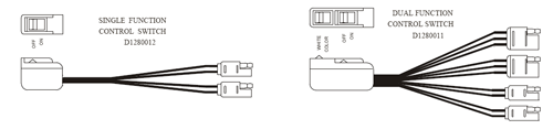
Control Switch:
A lighted costume needs a Control Switch to turn the battery power on and off. Some costumes need the switch function to control both power and color change. This switch is normally located in the left hand, which leaves the right hand free for shaking hands with the audience. In some costumes there is only a power switch which is located on the costume and is generally place just above the waist on the right hand side. This power switch can be Toggle, Rotary, or any good reliable switch wh ich satisfies the customer.
Disconnect Means:
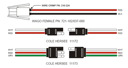
It is necessary to disconnect the battery from the costume in order to charge the battery. Normally the battery is disconnected after each performance or parade and connected to the charger and placed on charge. The recommended part for disconnecting the battery is either a Cole Hersee Plug or a Wago Connector.
Also, when a costume is made up of more then one piece, then it is necessary to add some means of disconnecting each piece. The standard recommended part for disconnecting costume piece s is the Cole Hersee plug (this is a water resistance type connection).
Special Disconnect Means:
One exception to using the Cole Hersee plug is when the costume is wired for 4-Circuit chase operation. When this is the case then a 2 pin and 6 pin Molex plugs is re- commended.
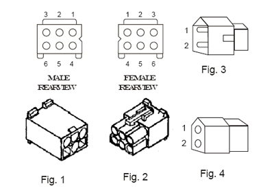
| Molex | Description | Poles | Fig |
|---|---|---|---|
| 15-31-1063 | Male Housing (Plug) | 6 | 1 |
| 15-31-1062 | Female Housing (Rect) | 6 | 2 |
| 03-09-2022 | Male Housing | 2 | 3 |
| 02-06-6135 | Male Pin – Gold (.062″) | – | 1 |
| 02-06-5135 | Female Pin – Gold (.062″) | – | 2 |
| 02-09-2103 | Male Pin (Tin) | – | 3 |
| 03-09-1022 | Female Housing | 2 | 4 |
| 02-09-1104 | Female Pin (Tin) | – | 4 |
NOTE:
1. Used on Costume Chase Lights.
2. Crimping Tool
Fig. 1&2 = Waldom #: W-HTR-2262-A-P
| Sager Electronics TEL: 800-724-3780 FAX: 800-268-8001 |
Sterlin TEL: 800-745-5500 |
Additional Disconnect:
Additional Disconnects that has been used on costumes. Each pin is rated at 5 amps continuous load.
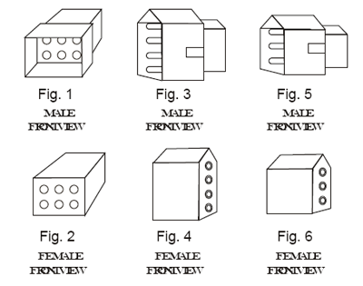
| Molex | Description | Poles | Fig |
|---|---|---|---|
| 03-06-2061 | Male Housing (Plug) | 6 | 1 |
| 03-06-1062 | Female Housing (Rect) | 6 | 2 |
| 03-06-2041 | Male Housing (Plug) | 4 | 3 |
| 03-06-1041 | Female Housing (Rect) | 4 | 4 |
| 03-06-2031 | Male Housing (Plug) | 3 | 5 |
| 03-06-1031 | Female Housing (Rect) | 3 | 6 |
| 02-06-2103 | Male Pin – (Tin) | – | – |
| 02-06-1103 | Female Pin – (Tin) | – | – |
NOTE:
1. Used on Costume.
2. Crimping Tool Fig. 1&2=Waldom #: W-HTR-2262-A-P
Polarization of Cole Hersee Conn:
The protected part of a connector should be the positive 6 volt side/s when the connector is not connected to the mating side.
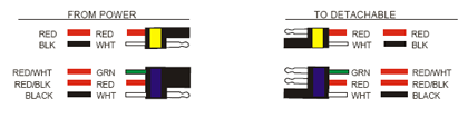
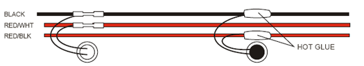
Typical Costume Wiring:
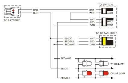
Cole Hersee Color Coding:
The Cole Hersee connectors are color coded with colored heat shrink tubing or 3M color tape .5″ wide. When color to color is mated, then the costume is connected properly.
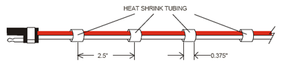
Dangling Connectors:
All dangling connectors will have short pieces of heat shrink tubing installed as shown in order to form a harness.
Lamp Wiring:
(a) Lamp leads connect to the 16 AWG wire with at least 1 1/2 turn around center of stripped section.
(b) The form of the lamp lead should be seen after soldering.
(c) There should be 1/4″ of Heat Shrink Tubing covering the insulation of the 16 AWG wire on both sides after heat shrinking.
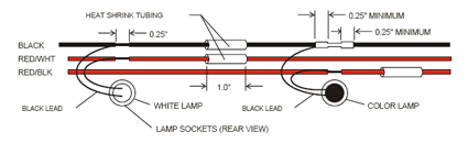
Two black wires can be installed on one connection point when the lamp positions are two close to maintain
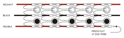
Hot Glue can be used instead of heat shrink to seal solder connections when needed in repair or new costruction.
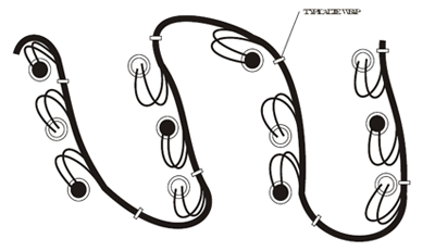
Harness Routing:
Routing of typical wiring harness in costume is shown below. Tie the harness down to the liner where needed to hold form and to keep strain off lamp leads (Typical 4 to 5 inches apart). The routing should form lazy loop in most cases in order to keep the costume piece flexible.
Guidelines For Wiring:
- Keep HEAT from heat gun away from fabrics.
- The maximum lamp count for filament lamps is 125 lamps per battery circuit with about 40 lamps on a branch circuit.
- The maximum lamp count for LED lamps is 250 lamps per battery circuit with 80 lamps on a branch circuit.
- The maximum cut or nicked wires while stripping is 2.
- The form of the lamp lead should be seen after soldering.
- The lamp lead connection should be made in the center of the 1/4″ stripped section of the wire.
- Lamp lead insulation cannot be mel ted into the soldered connection.